 As usual, if it can be done, I want to build it. I found the idea of making a powered kayak an irresistible urge. Sure, they make one for $499 that does the exact same thing, but I already had a trolling motor from an old boat sale. Why buy it when you can make it and I am too cheap to pay that when I know I can make it. 🙂
So to start out, what you are looking at is a Minn Kota Endure 40 (40 pounds of thrust) mounted on to a Ocean Kayak Prowler 15. It runs at a top speed of 4.6mph on 5 and 3.6mph on 4 and various on down and speed 2 is about 2mph and perfect for trolling. Even though 5 sounds like the speed you always want to use. 5 draws about 30amps and 4 draws about 16 amps. So for an extra .9mph you draw almost twice the battery life. So you can clearly see with a bit of patience and cruising at a lower speed you can make the battery last a lot longer.
This is the mount that I made for mounting the 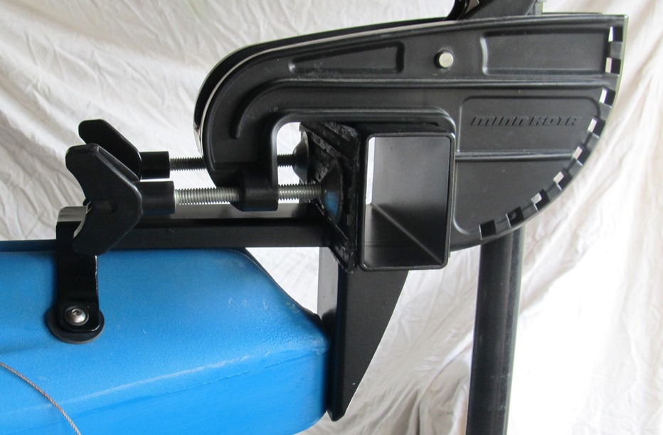 motor on the stern. I had some 2 x 3 channel laying in the shop and cut it out to make the mount. The the actual mount is just a long piece of channel. The riser is a smaller section and cut on a 45 degree angle to mount to the rudder screws. This worked, but it was clear that turning the motor on and off would torque the motor forward and backwards and apply excessive strain to the molded in screw mounts for the rudder mount. So I added another piece of channel cut long and thin to go over the rudder storage channel. I left part of the 3″ side whole to bend open and serve as ears to bolt the mount to really stiffen the mount. Then weld it all together, prime and paint it all.


The next part here shows the attachment of the mount. The red disks are polyethylene from and old RAM canoe that died in a previous life, but it serves great for backing plates for kayak mounts. Stainless Steel fender washers and nylon locking nuts complete the mounting hardware.
 You can see here the bent out ears made from the 2×3 channel and how they are bolted on with a rubber washer between the ears and the kayak and the bolt and the mount. This stiffens the mount very well and protects the kayak.
 Next is the access hatch that I needed installed so I could get access to install the nuts for the mount and wiring for the plug for the motor connections. I bought this access panel from Austin Kayak along with the front hatch you will see later. This was very cheap and cost about $3.50. I am pretty sure I spent almost as much on the SS screws to mount it as I did on the hatch itself. I added RTV glue to the access hatch before screwing it on and closing it up.

Now, we get to start on the motor and modifications to it. The top of the motor with the controls all needed to be removed. I saved the variable speed control switch and aluminum bar and connection for later on. The shaft was too long and need to be cut down about a foot. I did this with a hacksaw blade, but slowly and by hand so as not to cut the wires.
The 3/4″ PVC elbow I was trying to fit on to the  shaft would not slide on. My solution was to gently sand the top with a ledge smaller so it would slide on. I did this on my belt sander and it made real quick work of it. Then it slide on very easily. I used RTV glue to make the seal and threaded a 1/2″ long 10-24 bolt through the elbow into the shaft. The RTV glues to the elbow, but does not like grabbing the fiberglass or composite shaft. Tapping a bolt thread through the PVC elbow and into the shaft locks it into place.
This  is the Ranger trolling motor two piece plug and Here are the two pieces. The socket for in the kayak and the plug for on the trolling motor cable. Most other plugs will not handle the 10awg wire or are just not big enough and will probably fail due to the heavy current draw. This is a heavy duty plug and I put the tape measure in the picture so you can see really how big it is.
There are cheaper plugs out there, but you will be running 30amps through this and how high the inrush on starting the motor is, I don’t know, but its a lot higher! Spend the money and buy this plug!! There are not any other plugs this heavy and with 4 wires.
I got the great idea to use a fuse on the first run. I got a 30amp inline waterproof fuse from AutoZone and wired it in. On the first heavy test run I ran the motor on 5 a lot. One time I had the motor off and ran it right to 5 starting out. The inrush of current plus the load of a still kayak on the motor provided enough draw to not only blow the fuse. The fuse blew into pieces and deformed the plastic fuse holder enough to be unusable. You can send a lot of current through this, buy the correct plug!
I thought of moving up to a 50amp fuse, but then thought Minn Kota never had a fuse on the motor before. Maybe their engineering department know more than I did. 🙂
Now on to 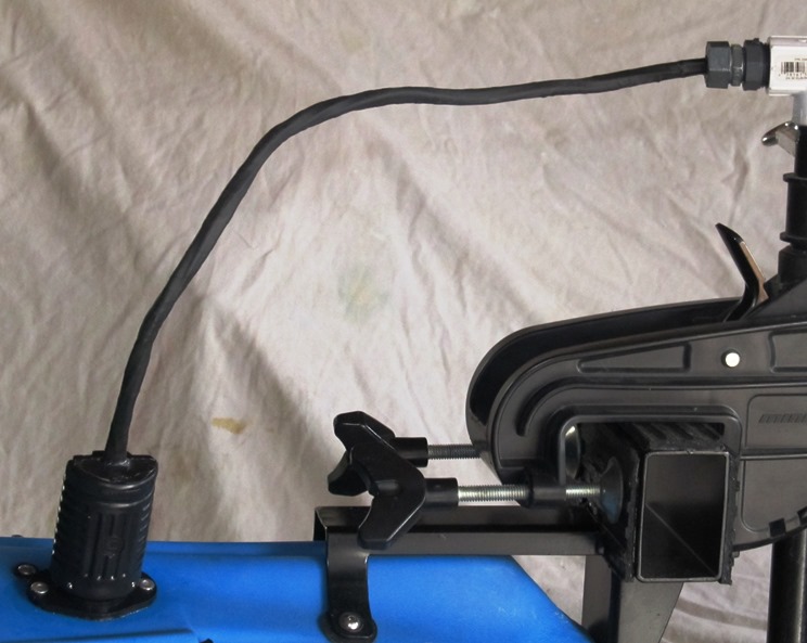 completing the wiring in the back. The PVC elbow is a slip to screw and that allowed me to use a 3/4 by 1/2 threaded reducer and screw a 1/2″ wet location gland over it. The wire was encased in heat shrink tubing and then the electrical plug was added. Each wire was fitted with a crimp connector to attach to the four terminals on the connecter. Make sure you fill each of the wire insert with dielectric grease before crimping it closed. This is very important as corrosion will build up in the connectors and some day in the future you will loose connection and have to remake the crimp connections.
The same for the plug in the kayak. Make the 4 crimp connection with grease and RTV it into place. Some water always gets into a kayak. its a moist environment. If you do not use the dialectic grease, your connection will fail, eventually.
Next  was the center hatch. I did not have one
  and had to install it to have access to the center. The first picture on the left shows the webbing as it some with the hatch. The right picture is the webbing cut out so I had a place to insert the control switch. This was just all carved out with a sharp pocket knife. Just shave a little hear and there. All done in a 1/2 hour while listening to music and it’s not as difficult as it looks.
For the switch to be mounted to the hatch I just 
 drilled a hole right when I needed to mount the switch so it all lined up in the area I carved out. Then took the hacksaw blade and sawed a slot for the key on the switch. Then again a bunch of RTV glue all round in the open area and pressed and clamped the control switch in over night to setup and stay there.
The right picture is the back with the switch RTV glued into place. The left is the finished hatch cover ready to be installed.
The picture on the right shows the cable being  connected to the switch. Notice the fuse, which I thought was a good idea, but blew leaving me stranded with only to paddle again. The left picture shows the knob slide on and ready for action.
Making the knob was pretty easy. 
 I drilled into a pressure treated 2×4 with a 2 1/2″ hole saw until it started. Then removed the pilot bit and drilled the rest of the way through. Then ran a Fresnel bit in to make the opening for the aluminum rod. The bottom of the left picture is the exact parts that connect to the switch before taking it a part. I just cut it off and epoxied it into place. The top numbering was made in AutoCAD and I think there is a 28 degree turn per snap of the switch so I can see exactly what speed I am on. The knob just slides on and off and I just put it in the backpack on my seat when transporting the kayak. I just put several coats of varnish on the wood to protect it. The paper was seated on a light coat of varnish like glue, allowed to dry and covered in various more coats to seal it in.
The Battery 
 ended up behind my seat as there was no room in the Prowler 15 up front with the battery up right. I should have bought the more expensive AGM battery which could have went on its side. I would recommend this if you start to make your own as it helps balance the load better. I used some of the extra plastic to make a cover for the hole for the battery wires. I could not get the nut for a gland connection to the spot. My arms just would not fit back there. I also cut the bottom of a battery box off to cover the battery and strap it down. You do not ever want to see a battery short out and it would melt holes into your paddle, net pole or what ever touches those terminals as well as destroy the battery.
That is about it.  Size the links for your rudder cables and replace with chain or what ever you need to make it link up. This rope was just a temporary solution to make sure I got the length correct. Now get out on the water fishing!

Wow, that is a really impressive set up. I had a friend that did a custom set up like this for his canoe, but I haven’t seen one like this on a kayak. It’s awesome.
LikeLike
What kind of switch did you use?
LikeLike
It is the same switch that was in the original motor. It is just relocated and rewired.
LikeLike
I don’t have a control switch, just the original arm that twists for forward & reverse. Where can I find a control switch like yours?? tom jones in tulsa
LikeLike
Tom, my switch came from inside the trolling motor head and was turned by the original arm coming out of the head. I just took the head apart and reused the pieces.
LikeLike
Very nice work. I want to try this too. Thanks for sharing your ideas.
LikeLike
When you remove the top cover and the speed control, you’re left with four wires coming out of the shaft. I have the endura c2 30 and it has two 14AWG wires and two 16AWG wires. How do I lengthen them? Can I use 10 gauge wire for all four of them to go into the back of the male plug? Butt connectors don’t work. In stuck at this part of my build. Thanks.
LikeLike
You just need some stranded wire. Any size larger than what you have and 10ga will be fine for the 2 14’s. you could use smaller wires for the control wires.
If butt connectors will not work I would suggest solder and tape. Strip wire at least a 1/2″ maybe and inch, twist them together and bend in half and solder the connection then tape it. Make sure the wires make a good physical connection before soldering. The solder will prevent corrosion in your connection. Radio shack carries 30watt soldering irons and get some rosin core solder.
LikeLike
I got the motor connected to the back of the male plug without a problem. Im having issues with connecting the throttle control to the back of the female receptor. What size wires did you use for the female to the throttle control? I’ve tried 16 and 14 and the yellow wire got fried. I’ve tried all 10 guage and the battery wires overheat. I used the 12v diagram for the plug setup. Seems like the power isn’t going past the plug connection. Maybe I got a bad plug? Im
LikeLike
I used all 10 Gauge on the 40 which should draw more current than your 30. Are you running the motor from stopped to 5 right away? If so try slowly stepping it up. 0 – 5 quick makes a huge power draw.
Make sure all of your connections are good. Bad connections make resistance.
I don’t understand the throttle control and female receptors. Are you talking the built in throttle and spade connectors on the wires?
LikeLike
Did you ever figure out why the wires were melting? I am having the same problem. Stuck.
LikeLike
Brian, I never had any problems with wires melting except when I had a fuse and it heated and blew. Wires melt due to the amount of amperage going through a wire. You either have too small of a wire, too much amperage on that wire, Either way you need a larger gauge wire. Or a loose connection which in effect makes a larger wire act as a smaller wire at the poor connection.
LikeLike
Rob. Thank u . I figured it out tho. Very stupid on my part. I followed the paper directions that came with the plugs and left the jumpers on the back of the plug. As per 12 v setup. After thinking about my problem I realized that the jumpers DID NOT belong on there for this application. Duuhhhhh… Thank u for your Timely response. Much appreciated. FTW247
LikeLike
I don’t understand how you got 6 wires through the plug that only has 4 positions.
LikeLike
There is only 4 wires that leave the trolling motor through the plug. So it is only 4 wires running through the plug.
There are 6 wires on the control switch, 4 that come from the trolling motor and 2 from the battery. This might be were your confusion is coming from.
LikeLike
Ok, why do I have 6 wires. Maybe cause it has reverse? I have red/black battery. Red,yellow, white around the outer spades. There’s another black in between the 2 battery wires.
[IMG]http://i258.photobucket.com/albums/hh251/wetline0005/0DEC6BCF-AA92-407A-9BB7-D5D00034CC90-21284-0000061D6F47803B.jpg[/IMG]
LikeLike
You have 6 wires to the control and so does everyone. 2 go to the battery, only 4 go to the trolling motor. Black, red, white and yellow go to the trolling motor and the and flat 2 wire cable go to the battery and not through the 4 pin plug.
LikeLike
Never mind I got it. I was messaging while at work and didn’t know what I was talking about. Got it. Thanks.
LikeLike
Aloha, I am liking your setup, anyway you would be able to reproduce the motor mounting plate? I would gladly pay for your efforts..Mahalo Jeffv808
LikeLike
Sorry, not very interested in fabbing another one. I kind of custom made it to the Prowler. New England Kayak message board has a good thread on cutting the motor mount bracket to mount on a kayak.
LikeLike
LOL, Yeah I was hoping someone would have some pre fabed mounting plates, I was able to bend a pc of aluminum and have my buddy weld up a block for the turn screws to bite into..Yeah like you I have no wish to fab another. Mahalo for you response.
LikeLike
Greetings from Idaho! I’m bored to tears at work
so I decided to browse your blog on my iphone during lunch break.
I really like the information you present here and can’t wait to take a look when I get home.
I’m surprised at how fast your blog loaded on my phone .. I’m not even using
WIFI, just 3G .. Anyhow, superb blog!
LikeLike
has anyone considered using the lithium 123 cells in a series/parallel configuration like the use in model aircraft? They are getting cheaper, I have a load of them, and hope to have a battery that will be lighter with more charge density to power a 12′ Pungo. I like the motor mount, did you use aluminium or stainless, or just relying on paint for anticorrosion?
LikeLike
I did not use them but you should read this thread by Langston (Metro Man). He used the Lithium Ion LiFePO4 batteries in his kayak. He was able to reduce weight from 50 pounds to 20 pounds but the battery costs over $300. You can read about it here.
http://www.snaggedline.com/showthread.php?2537-Conversion-to-Lithium-Ion-battery-power&highlight=battery+metro
LikeLike
Thanks for the follow. I am just starting my set up. My kayak is a Prowler knock off. But a good boat. I got a new C2 Endura 55. Thanks for the wiring explanation. I am building a mount but similar to another site and includes a hinged mount for tilting the motor. Steering is with a handle rod as opposed to foot pedals. Right now it’s too cold here to work on the project.
LikeLike
I’ll wait to see yours on your blog. You’re doing stick steering?
LikeLike
Yes I got the idea from this site; http://www.kayaktrollingmotor.com/
I don’t know I might even buy the handle set up. It’s $85 and i can’t think of any hardware that will attach to the motor shaft like theirs does.
LikeLike
I personally would go with a rudder cable to a stick steering shaft on the rights and a spring on the left of the motor. It might be more difficult to work out, but would be a cleaner installation.
But what ever you are happiest with is the best. 🙂
LikeLike
This is outstanding . exactly what I am going to do to my kayak . most of the so called kits out there are absolutely crap and overpriced Chinese made inferior products I like your design it has given me some ideas .. thanks
LikeLike
It is appropriate time to make some plans for the future and it is time to be happy. I have read this post and if I could I want to suggest you few interesting things or suggestions. Maybe you can write next articles referring to this article. I wish to read more things about it! ceffgdabdkdd
LikeLike
archeryrob – I have the Future Beach knock off of the prowler. The stern is very similar. I am working up my bracket now. Question. Do you have a way to engage the motor tilt release from your seat to lift the motor for shallow water or beaching?
LikeLike
No, I never did anything with that. I experimented with a rope squeezing the release and pulling it up, but never finished it as I only used it in deep water like the Chesapeake. Bass yaks has a lever they install and a few guys have copied it online.
LikeLiked by 1 person
http://www.stripersonline.com/t/805499/building-an-electric-drive-kayak
check out this idea for the tilt. Though I don’t know where he got the material to make this pin or how he remove the existing pin it is a genius idea
LikeLike
That is Bob Miller from NJ, he runs the Susquehanna kayak jamboree every year. If you want to know more, you should just track him down and ask him.
LikeLike
Love the idea i would like to make a mount for my kayak and keep it like yours but wan a make it so there is no drilling any ideas?
LikeLike
If you could have bars up to the Slide Trax if the rear of he kayak has that. You need more than just the rudder mount to stabilize the motor or the torque will at the least loosen the bolts and at worst pull out the nuts cast in the kayak for the rudder mount.
LikeLike
How did you do about extending the stock wires from the motor shaft 2 10g wires a 16g and 14g. You mentioned that all your wires are 10g. I’ve bought 2 8g wires and bout a 14g and 12g to increase the size. Your saying that this will burn up. Also what did you use for you wire shething tot cover groups of wire.
LikeLike
I bought a cable from Lowes that was 4 10ga stranded wires in side of a black cable casing. I made all connections inside of crimp splices and inserted dialectic grease inside of each crimp connector to prevent corrosion.
LikeLike
But at some point you had to connect the.10 gauge to the original 14 n 16 gauge wire or did you go to the motor 100%
LikeLike
I spliced the 10ga wire to the wires coming out the top of the shaft.
LikeLike
Hi Rob, I took your advice and I am using the power supply power plug from TH Marine. I have a Minn Kota Endura 55 trolling motor and I have decided to use the electronic throttle controller from Minn Kota instead of using the factory throttle control. My question is that I am unsure of how the TH Marine is wired with all 4 wires red, black, white and yellow. Do I use the metal bars that were provided with the power plug or discard those? What are the white and yellow wires for and were would I connect them after they are wired to the power plug? The Minn Kota Electronic Thottle Control has a pretty good wiring diagram that I can email you, but I don’t see where the white and yellow wires would go? Can you help me?
LikeLike
You need to remove the metal shorting bar, as you want 4 separate connections. The black and red and straight power and the white and yellow to send reverse and speed control signals to the motor control module in the nose of the motor.
I can look at the wiring diagram, But I do not want to post my e-mail address out her eon the open website. See if you can e-mail be through WordPress and I’ll see if your login has your e-mail.
LikeLike
Pingback: Ride 135 Blind with the Dog House | Confessions of a fisherman, hunter and tinkerer·
Absolutely fantastic! I too just finished my set up with an Ocean Kayak Malibu two XL and a 55lb Prowler from BassPro. I went the PVC route as i live in the Bahamas, have zero tools, wanted the mount and motor to be removable. I have been stuck on finishing my wiring. Iv extended and run all the wires but still need to connect the 4 wires from motor to control. Ill try to post up pictures.
LikeLike
Can someone please advise how to post up my photos the way others did above?
THX
LikeLike
I do not think you can post pictures in the wordpress comment replies. You can post them to photobucket, or tinypic,and post the link to them here. The pictures above where posted as its my blog and I can post pictures when I write an entry, but even I cannot post a picture in a reply. I do not know if an [IMG] coding link for a picture will work here
LikeLike
A test
[img]https://archeryrob.files.wordpress.com/2013/04/22_knob.jpg?w=470[/img]
So, I tried linking one of the above pictures and it will not accept the coding to post a picture.
LikeLike
Is there a specific reason for using the Ranger trolling motor two piece plug? Could you not just extended the wires coming out of the trolling motor to where your switch (knob) was located?
LikeLike
Yes, you could run it direct, if the motor stayed permanently attached. I wanted mine to be removable as its hard to carry the kayak with it so heavy in the back.
LikeLike
That’s what I thought but just wanted to make sure. I am needing to do this on my pontoon boat. Now for my next question….I am going to hook up 3 trollers to my boat, can I take and connect all the wires from each and run them with just one knob?
LikeLike
I am not sure the knob the switch is on can handle the amperage of three motors. The contacts probably are not rated for the in rush that would be created starting up to move. You need to call the trolling motor manufacturer to get the ratings of the switch. They mostly likely will not help for liability reasons with customizing their product.
LikeLike
Some of the trolling motors I’ve looked at have circuit boards or other electronics in the head. I take it yours did not have anything in the head other than the throttle switch?
LikeLike
no, just a switch and controls sealed in the motor nose. I blew a 30 amp fuse with just one motor, a minn kota 40 with the in rush going to 5 speed from a dead stop. 3 motors could be 100 amps through the switch!! i would evaluate draw and re-evaluate everything. You might need #4 wire or something that large from the batteries. I also assume one battery would not be enough unless you get one of those huge diesel engine batteries like on generators and I don’t think they make those in deep cycle.
LikeLike
Archeryrob, awesome work. Question for you or anyone On this thread? I want to be able to control direction/speed from the seat of my kayak. I know very little about this stuff. I want to get a Minn Kota SP riptide 45 lb saltwater transom trolling motor and get a foot controlled pedal/steering. Can I connect this foot control to a transom mount motor , then wire it through the yak and control everything from my seat?
LikeLike
I don’t know much about that motor, but as long as its all wires to the foot control you can extend it. Some old motors used cables like a bike brake to make them steer.
I would also check on the foot control be able to be submerges if you roll the kayak if its not you could ruin the controls.
LikeLike
I love what you did and am trying to duplicate it but the connector you show and the one I purchased is a 3 pin connector pair. As you say there are 4 wires on the control switch so the question is how do you wire the 4 wires through the 3 pin connector?
LikeLike
Sorry about that, I took a closer look and ordered the exact connectors which are 4 pin not 3 as I had thought
LikeLike
Hay! Planning on moving my controls to the front some day as well(right now just using an extention), I have the same motor,Little idea for you if you want… i drilled a small hole in the lever to bring the motor out of the water and rigged up a brake cable system so i can bring the motor out of the water when coming to shore etc. little squeeze of the brake lever, little pull on rope, release handle and everything locks back up.
LikeLike
Cool, thank you, I hope you shared that on a kayak forum somewhere. I hope someone else can use it as I sold this kayak and motor 2 years ago when I got the Ride 135 to take the dog hunting.
LikeLike
Rob. I used your article, others ideas, and even BassYaks in CT. I modified ideas from all. And for ease and time I just moved the entire control head to the rod holder near my seat and use it there. A few more mods are needed yet. I made the tilt system above deck with topes. A little cluttered but workable. Using Minnkota endura 55. fun!
Terry. I also posted back in 2014
LikeLiked by 1 person
Great instructions and pics. I am getting a Native my first kayak. It has a trolling motor mount and the handle was separated and moved to beside the seat. The steering controls are cabled to the handle. It is something I want to change. Your speed control Idea is perfect . The set up allows hands free for fishing while low speed and steering with foot. Your bracket idea it perfect. Nice Job
LikeLiked by 1 person
Thank you, I wish you the best with your build.
LikeLike
Pingback: Kayak trolling motor stern mount – My Blog·
Pingback: Kayak trolling motor stern mount – Famous Last Words·
Pingback: Kayak trolling motor stern mount – Fishing Ideas·
Pingback: Kayak trolling motor stern mount – Outdoors·
Pingback: Kayak trolling motor stern mount – Outdoors Ideas·
Hi Rob, I have the Aire Inflatable Lynx 2 and built a side mount for my endura 30 from wood and works good. Now I want to try a transome mount. I cut down a sturdy dolly and strapped it down. Put the 40 lb battery 3 feet away. I would like to lighten it up and just do better. Anyone you know doing transome mounts for the aire lynx 2 or superlynx? Thanks Rob! Finn
LikeLike
The best way to lighten it would be to change to Lithium batteries. I never did that and this is a good place to read up on that. http://www.snaggedline.com/showthread.php?2537-Conversion-to-Lithium-Ion-battery-power Metroman is a guy named Langston that chnaged out to lighter batteries, but it is not cheap.
I do not know anyone else using inflatable kayaks.
LikeLike