It is always great being a tinkerer and someone else enlists your skills for their projects. Then you still get to tinker and make things, but you can do it with “their” money. 😀 Life can’t get better unless beer was free and didn’t get warm. Such a thing happened this year as my buddy Kevin and I were talking about how it was so warm last year and we didn’t kill any deer early because we self butcher. When it is warm you have to break the deer down to buckets in the fridge fast and that is a lot of work just after you tracked and dragged a deer out. Kevin said “Let’s build a cooler” and we started on design.
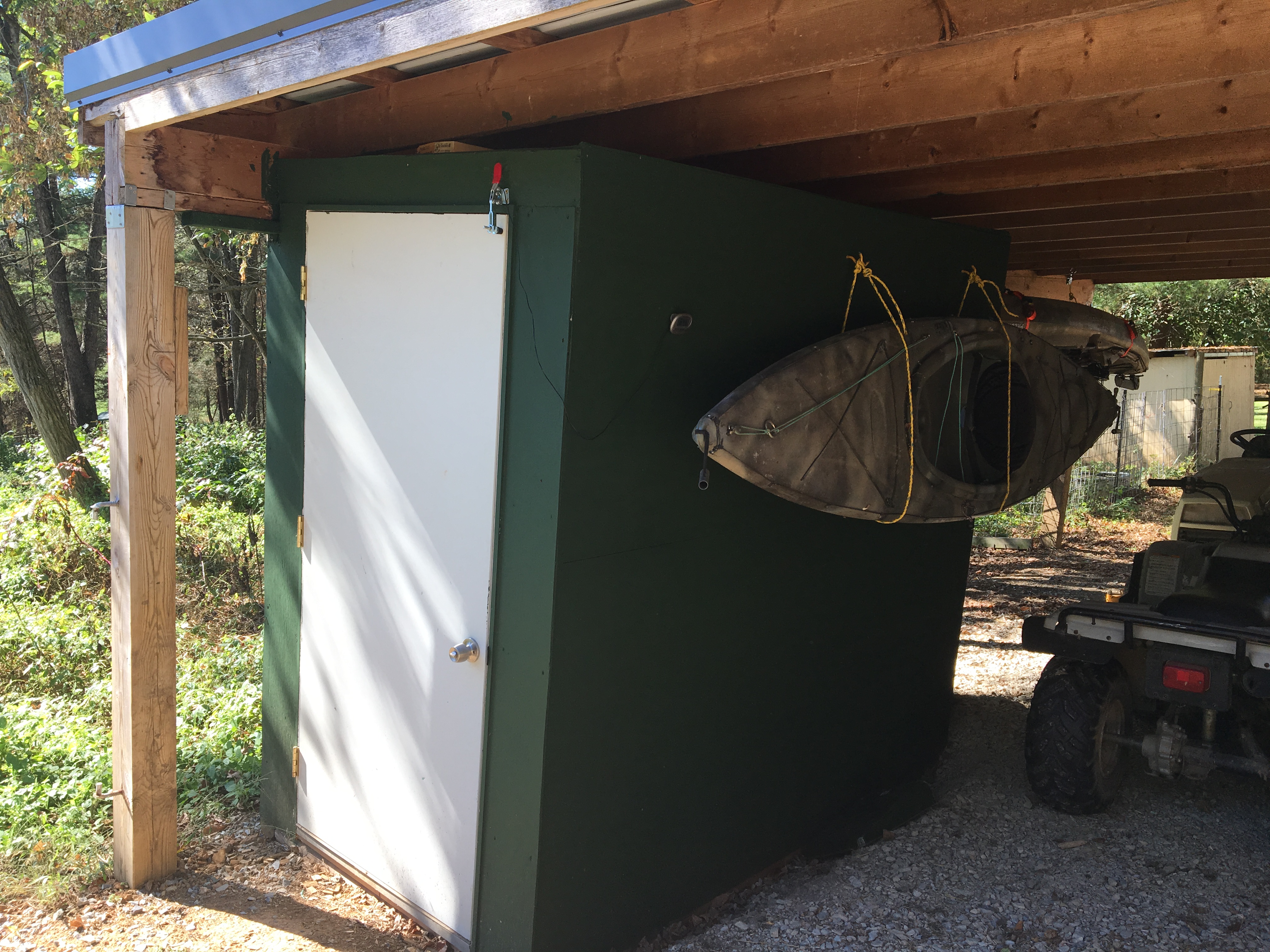
I am not going to go much into building the cooler frame as its just 2×4’s on pressure treated landscape timbers with a stone floor built under his shed roof off his outbuilding. Kevin bought the 2×4’s, I had almost all the R13 insulation left over from my garage refinishing, we got a free exterior door from another buddy and he got a deal on 1/4″ plywood on Facebook marketplace. Then he bought a cheap used air conditioner and we built what you see here with a hole for the air conditioner. If you need to buy a new air conditioner this one is pretty cheap and 5000 BTU’s.
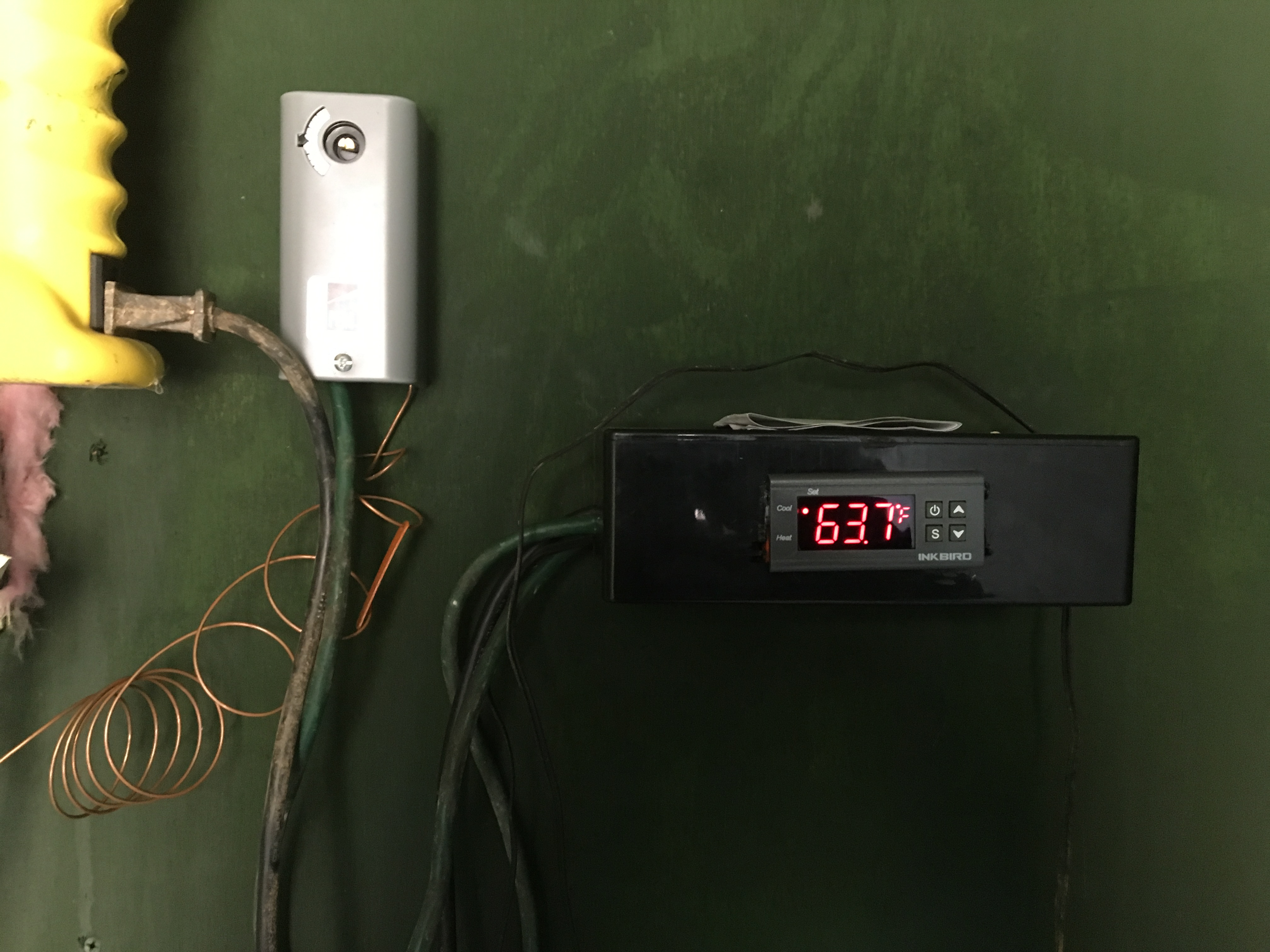
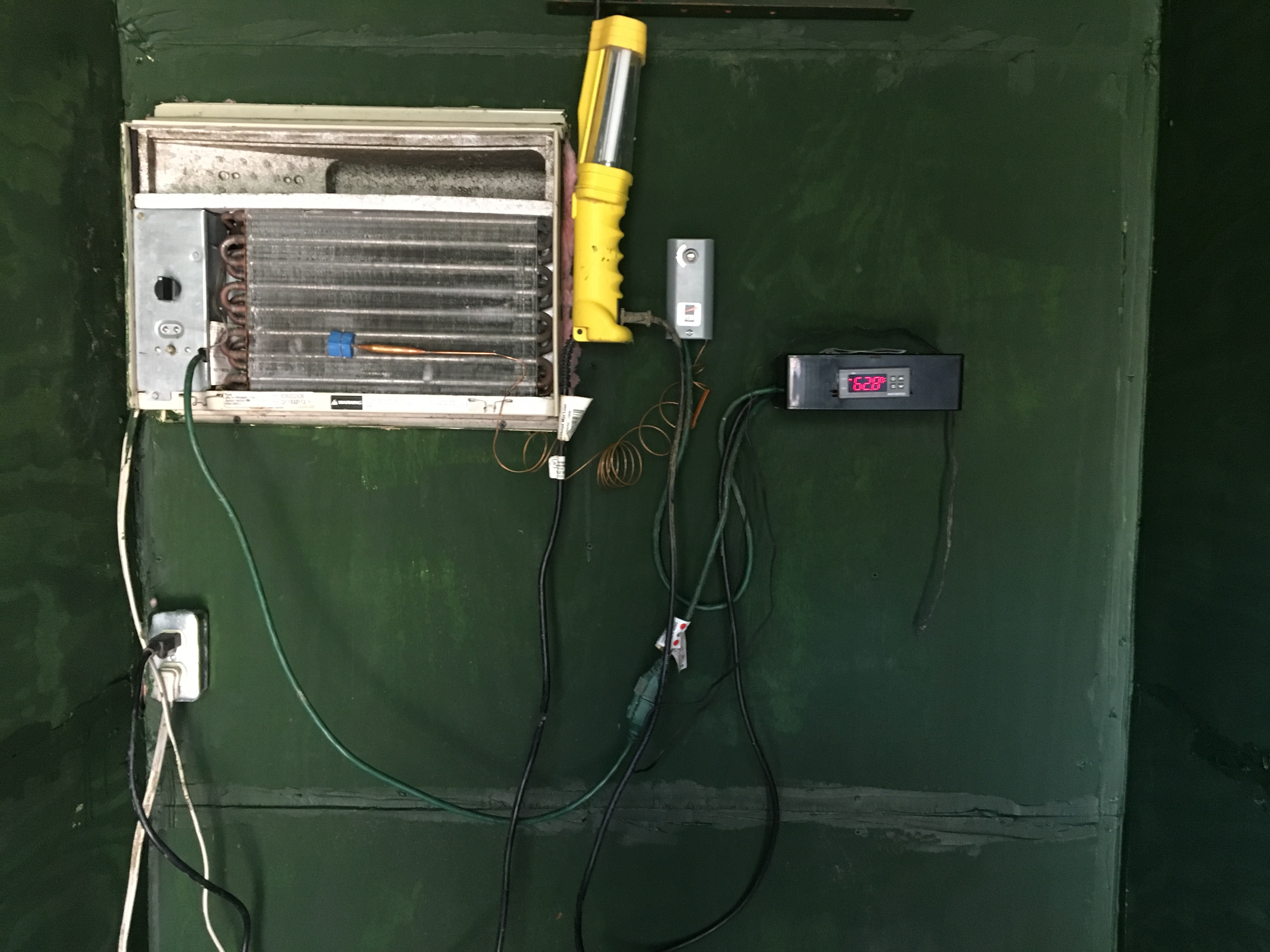
Kevin saw the price of the Coolbot controller at over $300 and texted me to assign my engineering resources to perform this task as a more cost effective price range for an alternative. I did my research and told him to buy the Inkbird controller ITC-1000 for $16 and to get the mounting box for under $24 total for both. I told him I could make it work with it. This would control the compressor and when you switch the air conditioner on the fan runs 24/7 and the inkbird tell the compressor when to turn on and off. Below you can see the final setup and the inkbird is on the far right. It and the air conditioner was all we started with. The Inkbird is set to run until 40° and this was just taken when the unit was off. The Silver box was added later for the failure you’re about to read about.
So initial tests seemed to work and we got the room down to 50° in a few hours. The coil was icing but everything seemed to be OK. Then in the beginning of October my daughter shot a doe. Everyone is cheering, she got a deer and a real test for the cooler. We hang the deer, start the cooler and have some beers and watch the cooler. It looks good and Kevin goes out and checks it before bed. Its only down to high 40’s and iced, but its running. He wakes up Sunday and it tripped the GFI from being over loaded, ice dripping or something and working too hard and its 55° in the room. The deer is cold still, but it is time to eat eggs fast and start butchering.
That was a failure because the freezing coil is straining the compressor. The air conditioner is not designed to be a cooler at 40°. So I had to figure out how to keep it from freezing up the same way a Coolbot does. So I looked around and found a Johnson Controls A19ABA-40C temperature sensor that would work. It would have closed contacts and open on freeze so it could turn the compressor off when the coils froze up. Then, when the compressor is off and resting the partially frozen coils are being defrosted by the running fan and still cooling the air in the cooler.
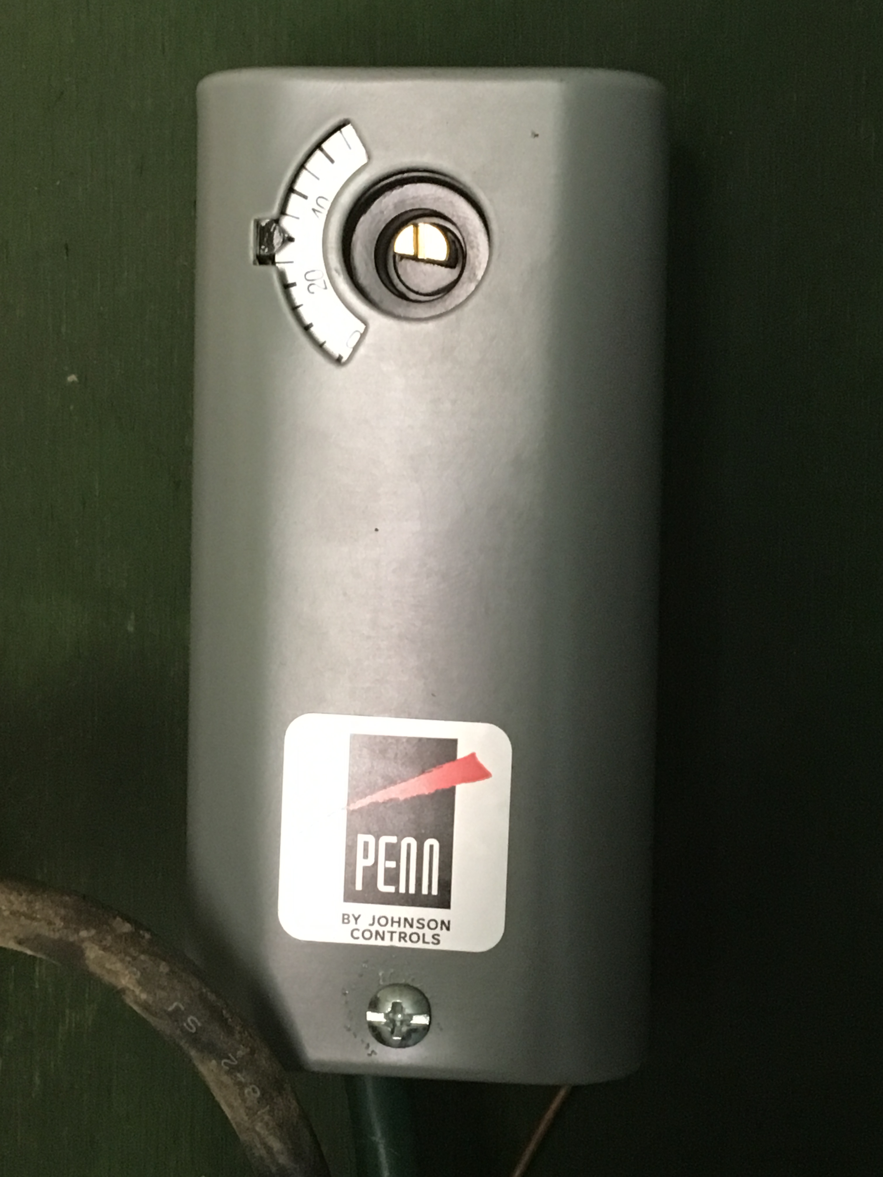
This was set to about 30° with about a 8° temperature differential. So when the coils reached 38° the compressor would turn back on.
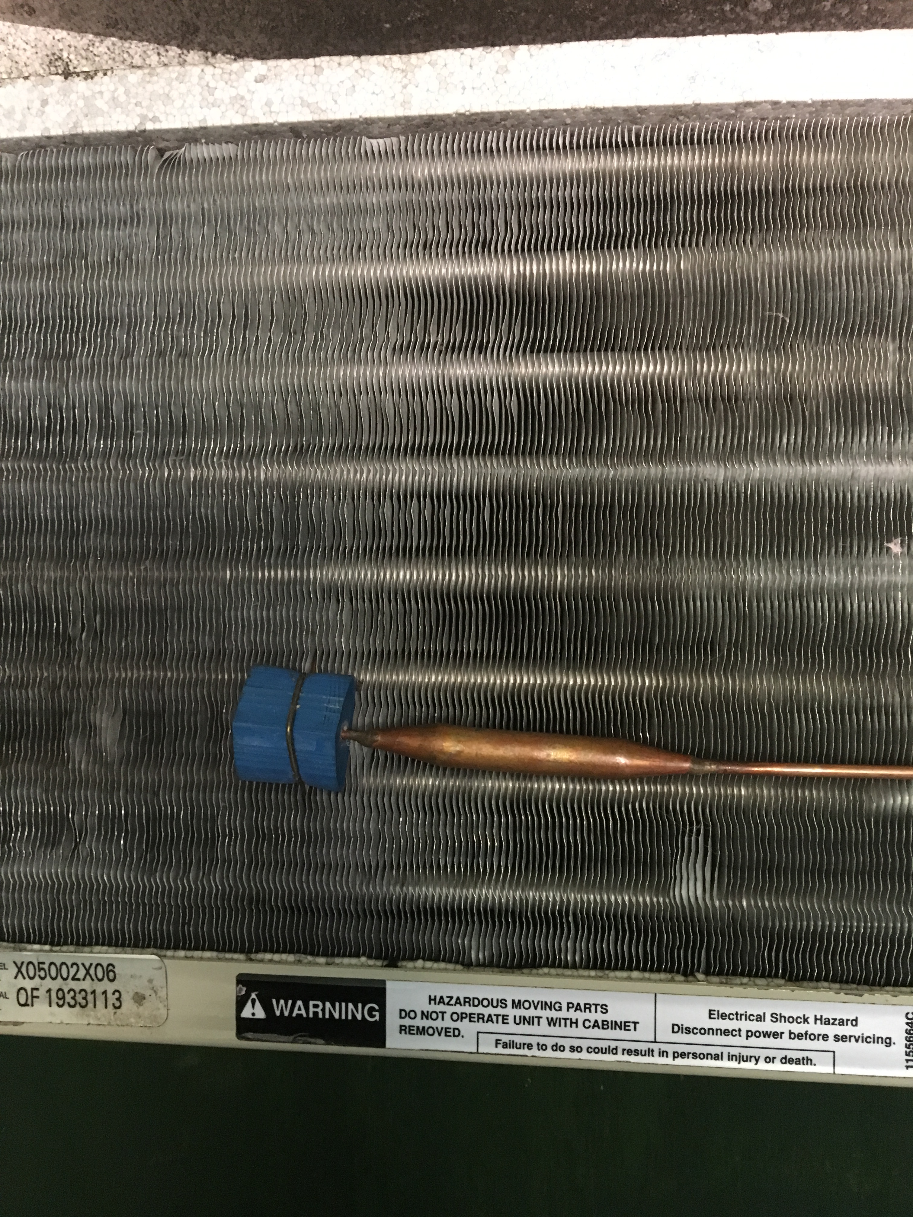
As you can see here I used the existing sensor mount and inserted our freeze sensor to lay flat on the coil. I had to bend the tip a few times to get it just correct to lay with light pressure against the coils.
Here is the wiring diagram. Most heat pumps and air conditions use the standard color of yellow for the activation wire for the compressor or pump start. I cut the yellow wire and inserted our controls instead of the existing control sensor.
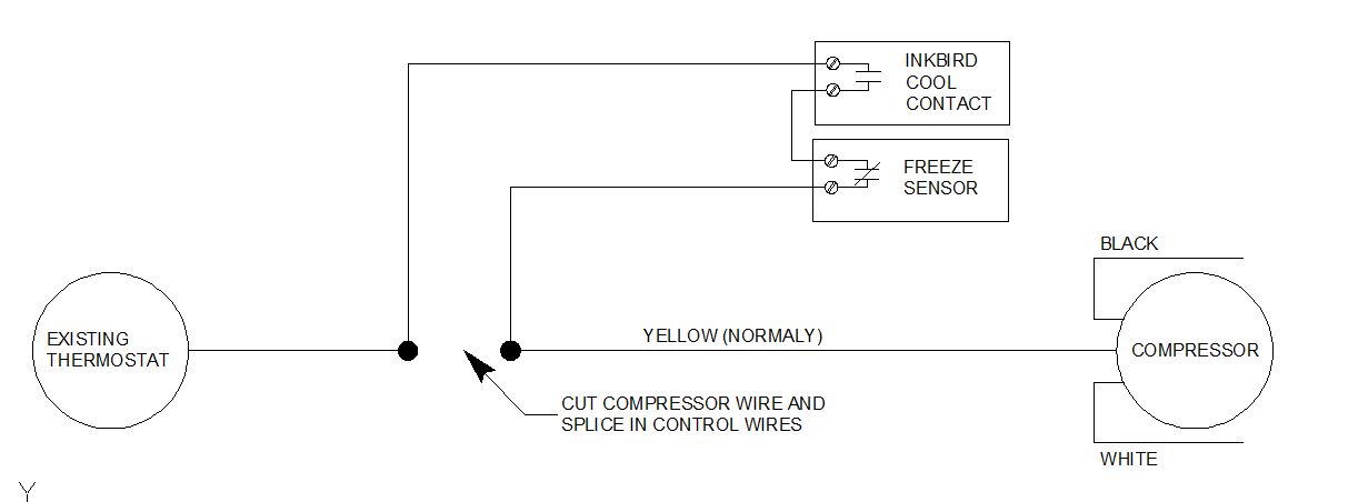
As you can see when you start it the Inkbird contact will close, or will already be closed because its warm in the cooler. When it gets to 40° this contact will open and stop the compressor. When you first start it the units compressors works overtime trying to cool the room. When the coil freezes the compressor is running for nothing. The freeze sensor senses this and will open its contact letting the compressor take a break until the coils melt out.
We ran a test like this for over 24 hours and you could hear the compressor turning on and off occasionally as needed. Some ice was on the coils, but it worked perfectly and we maintained 39° – 40° all the time.
Now you too could Redneck engineer a Coolbot on your own. The Coolbot sells for the cheapest I have seen for about $330 and I think we have less than that in the entire cooler.
Enjoy!
Rumble video added now.

Could you use 2 inkbird controlers inplace of the Johnson controler??? Any wiring info would be great to. Thanka
LikeLike
The inkbird only closes on the cold sense and I needed one that would open on cold to disconnect the compressor wiring when the coil was frozen. I did a wiring diagram above, its just wire wires to break the yellow compressor control wire to my more control equipment.
LikeLike
sorry to bother you but what do you have your parameters set at i keep iceing up and what is done with the original temp bulb
LikeLike
Open contacts at 30 to drop the compressor and closed contacts at 38 to start the compressor when called.
LikeLike
do i connect the black to black and white to white and yellow to black from the existing ac thermostat to the ink bird and the the same from compressor to the f johnson control don’t want to flow anything
LikeLike
I am not understanding your question. The black and white to the compressor is power and should be left alone. Yellow is the start wire. and should be switched by the Inkbird and JCI temp probe as shown in the diagram above.
LikeLike
gotcha i got confused when you were talking about hooking up the yellow wire you mentioned black to black and white to white and didn’t see that on the diagram thanks
LikeLike
I am going to try this have my cooler built. Two questions looks like the AC units existing thermostat stays in use will it go low enough to cool the cooler and does the Inkbird have a temperature sensor that penetrates the cooler to control the cooler temperature.
LikeLike
The air conditioner existing thermostat is still in it and I didn’t bother with it and it hasn’t caused any problems. I mounted the inkbird inside, but it could go outside. It has a 10′ cord for the temperature sensor that you can run inside. .
LikeLike
Have one more question if you could help me I purchased a used Frigidaire 8000 BTU the wiring harness has there wires going to the compressor black blue and red the black and blue go to the capacitor the red goes to the control board , it has 120 volts when you turn the unit on if I run the hot side to the solid line side of the Inkbird and the compressor side to the broken side would this be correct , don’t won’t to burn my equipment out experimenting. Thanks for the help this is a budget savor.
LikeLike
I am not familiar with that wiring and I am NOT a HVAC guy. You might want to find some other forums to ask on that wiring. Yellow is typically compressor on wire and I am not sure of the board you referenced.
LikeLike
user e-mail deleted. I contacted you directly.
LikeLike
Got my cooler built and running the Johnson control is hard to get right as you indicated, I ordered a extra Inkbird was wondering if I could wire it in line and set it say 2 degrees below the other and insert it in the fins like the cool bot does. Your opinion would be appreciated.
LikeLike
I assume you could use a second inkbird and put its sensor on the air conditioner coils. You might be able to set the sensor on it for 30° and then set the DS (Difference Setting) for 9°. I am assuming you would use them both on Cool. I don’t know if the coils will affect the sensor, or not.
Inkbird 1 – Cool contacts set at 40° and a Standard DS of 3° sensor in the air.
Inkbird 2 – Cool contacts set at 32° (Varied based on performance) DS for 9° and sensor on the coils.
This is my assumption and you’d have to practically test it. Comment back to this for how this worked or did not.
LikeLike
Wired in the second Inkbird this morning have the room Inkbird set at 37 with a 2 degree difference. Put the second Inkbird sensor in the fins like coolBot does set it at 34 with a 2 degree difference workin smooth no adjusting , thanks for the help sometimes we just need someone to bounce an idea off of.
LikeLiked by 1 person
Jack, do you have a wiring diagram for using 2 inkbrids? thank you. I ordered 2 for my hydro room and don’t know where to start.
LikeLike
Can’t speak for jack but I am pretty sure he used the same wiring as I with with the freeze sensor and just substituted the second inkbird in its place. You would need to use cold side for both as the second inkbird needs to be closed except when the coils is frozen.
LikeLike
Forgot to add the coil sensor is running about 1 degree under the room sensor.
LikeLiked by 1 person
What are your temp settings? And differential settings as well ?
LikeLike
I think the Inkbird is set to 35 or 36 and the Johnson controls freeze sensor at 30 – 38
LikeLike
Hey, archeryrob. Thank you! Great post! I appreciate the info. Since you first posted, have you tweeked the system?
LikeLike
No, it still works and doesn’t have any problems that we know of. The only tweek was adding the freeze sensor to make a thaw cycle for the coil and that was added at the time of writing.
LikeLike
None of the wires in my unit are yellow, but one leg of 120v goes through the compressor relay(black) and the other goes through the capacitor(white). Which one do I splice into?
LikeLike
What is or where is the existing thermostat in ur colbot clone post
LikeLike
It is just hanging from the ceiling. The temp wires are about 6′ long.
LikeLike
i know this is a couple years old hope still available my question is what do you do with the ac scencing bulb from ac unit
LikeLike
I think there is a wiring diagram to view, in this thread…
LikeLike
I replaced it with the Johnson controls freeze sensor. I think I just tucked it in side, but don’t remember.
LikeLike
could you send me a complete wiring diagram of the jonson control and ink bird power feed and all
LikeLike
The only wiring change done on the air conditioner was breaking the yellow wire though the inkbird and JCI temperature stat. That drawing is above.
LikeLike
Sorry, didn’t specify , it’s a 240v unit.
LikeLike
I wish I could help you more, but my knowledge of 220 is it hot both ways, so either side. I know nothing about 220v AC Units except the one at my house is and it used yellow as the compressor starter with seperate power also. It looks to me like the 220v units have a starting capacitor that gets dropped out., BUT I do not qualify as an air conditioning expert. So please do more research and post back.
LikeLike
Thanks, I appreciate the response! I just realized I know a good AC guy I can ask. I’m just another redneck trying to solve a problem I don’t quite understand.🙂
LikeLike
Cool, just remember to post back. A lot of people read this and I can only post from personal experience. Others could have the same issues as you.
LikeLike
Pingback: Ohio Brooder with Temperature controls | Confessions of a fisherman, hunter and tinkerer·
I used 2 Inkbirds in series. The first one is set at 0 degrees C, and has the sensor pushed into the fins of the air conditioner. The power for the second Inkbird comes off the “cool” terminals on the first one and is set at 4 degrees C. The cool terminals on the second on control a night light bulb that is wrapped around the air conditioner’s original temperature sensor. Works like a dream – the light comes on a cheats the sensor into thinking the room is hotter than it is and the first Inkbird prevents freeze up. You couldn’t ask for an easier set up!
LikeLike
Good, i’m glad it all worked out for you and you have a working cooler.
LikeLike
Great post man!
After a successful completion of this project I think I can qualify to wear the official title of a TINKERER. 🙂
LikeLiked by 1 person
Very informative and simple enough for even the non-tinkerer in me to try.
– Am I right in assuming that this method only controls the compressor, and that the fan is ALWAYS ON?
-If so can the noise be at tolerable levels for KITCHEN ADJOINING/ACCESSIBLE cooler???
LikeLike
Yes the fan always stays on.
LikeLike
Mike how did you wire the 2 ink birds in series ?
LikeLike
Mike did that. See the picture above and one inkbird becomes the freeze sensor and is placed on the refrigerant coils to open the circuit when the coils freeze up.
LikeLike
Would this system work with a portable air conditioning unit? It is a 115V 60HZ 8,000 BTU 8amp unit.
LikeLike
Yes, you are just controlling the compressor on and off.
LikeLike
Rob
Do you have pictures of the wiring connections that you did on your deer cooler for the inkbird? The diagram you show and the wiring diagram that comes with the inkbird don’t look anything alike. It’s a little confusing. Do I need a power supply to the inkbird? Some photos of the actual connections would be very helpful. Thanks
LikeLike
I do not have drawings, but if you got the ITC-1000 Terminals 1 & 2 are 120vac power. Terminals 3 & 4 are where the temperature sensor go. 5 & 6 are for heating and not used on this project. 7 & 8 are the terminals for cooling as shown on my drawings.
LikeLike
Hi rob, thanks for the quick response. I have one more question I hope you can help me with. The window unit I’m attempting to use doesn’t have a yellow wire coming out of the compressor. It has a white, black, and red. Do you think the red wire is the one I should use? Also they don’t come out of a thermostat directly. They come out of a capacitor. The diagram that came with the ac doesn’t show a thermostat location at all. I have no idea where it’s located. The ac unit has a touchpad for controls. No knobs. It does have a sensor mounted to the fins out front tho. I just want to make sure this gets wired correctly. Thanks. Any help will be greatly appreciated.
LikeLiked by 1 person
The red would probably be the wire to use, BUT I am not an air conditioning expert. That is the starting capacitor and that is what I used. I have black and white which are 120vac and the other, normally yellow I thought, is the control wire/trigger. I would cut it and splice it through. Worst case you just splice it back together if wrong. All you are doing is opening and closing that wire to control the starting capacitor which starts and stops the compressor. At least as I understand air conditioners. I can’t help with the push button controls.
LikeLike
Thanks for the help rob. I’m gonna give it a try. Fingers crossed
LikeLike
Reply back with success or failure
LikeLike
Hello Rob, still working out the bugs on my cooler. I ran it for the first time overnight. Can’t get it to go below 60° in the room. I didn’t do anything with the original temp sensor other than move it out of the way and replace it with the freeze sensor. Should it have cut the old temp sensor off or remove it completely? It might still be controlling the ac. Thanks again
LikeLike
I’m out of my area of expertise here. You might need t ask an air conditioning guy. But I would amuse some other control in the air conditioner is limiting it.
LikeLike
Rob thanks for the quick response. Did you cut or remove the existing sensor in the one that you built? Or how did you bypass it?
LikeLike
I only cut the yellow control wire to the starting capacitor with the circuit I drew here.
LikeLike
Ok. I guess I will check with a air conditioning guy.. I don’t want to cut anything until I’m sure.
I might find a way to keep that senor warm to trick it. Thanks again for your help
LikeLike
did it work?
LikeLike
I just wired my inkbird to my portable ac (not a window mount) it has one exhaust vent. My wires are all different colours but based on the main board diagram on my ac unit I cut the wire red wire feeding the compressor. (I am not able to post a picture of the main board diagram of my ac unit). I have the ac plugged into power set as low as it can go (17 degrees Celsius) and have the inkbird controller powered and intercepted the wire feeding the compressor as per your wiring diagram. I have the inkbird set at 10 degrees Celsius. I had it running for 12 hours with an outside temp at 19 degrees and going down to 12 overnight. The room didn’t get colder than 17 degrees. Did I wire something wrong? Sorry for the long message.
LikeLike
I assume you are in Canada or the UK with the temp in C. I must remind everyone again, I an NOT an air conditioning expert on all models. I just got mine to work.
I controlled the “starter” for the compressor and made it run as long as I wanted it too. Without knowing about your setup I think you cut a power wire and not the control wire.
For me black (hot) and white (neutral) for you it might be hot and other hot with 220v. Those were my power tot he starter, but the yellow was the control wire. Maybe yours is similar? But the idea is to look for the control wire controlling the starting capacitor, which runs the compressor.
Remember, I am laying assumption base don not knowing what you have in hand and not being an air conditioning expert. 😉
LikeLike
Thanks. All good. Appreciate any input. Yes from Canada. I have just one red wire going to the compressor from a relay or controller on the main board. Only wire going to that relay is the black hot wire. I cut into the red wire. When I turn everything on the AC into runs like it should ignoring the inkbird. I’ll have to do some trouble shooting.
LikeLike
Rob, Morning… I’m thinking of building a cooler for beef etc… Do you have plans for the building construction ?? I’m even considering a monorail for the quarters… My lady friend would like horses, beef and maybe a pig or so… The horses would be for riding, HAHAHA…
LikeLike
Taller than we did. we were limited in height by the shed roof where we built it. I do not have plans for the room, just not too big the air conditioner can’t handle it. Walls are walls.
Build a hoist or block and tackle to raise it to the mono rail. We just welded a pipe on top of an angle iron. The pipe slide better and the angle iron stiffens it.
LikeLike
I have an insulated truck body that was an ice cream deliver unit… Only 6′ inside… I can’t use it… Gonna have to build a “room”… Good info on the monorail…
Did you see my “pork butt” ham …
LikeLike
I have not been on smokingmeats lately.
LikeLike
OK… Well look for it…
LikeLike
Hi Rob, do you happen to have some more details on wiring the Johnson controller? I’m feeling a bit dumb on where things go. Many thanks!
LikeLike
Look up on the drawing on the post. The Johnson control part is the freeze sensor. It opens the circuit to stop the compressor when it is too cold and the coil is freezing up and sensing element placed on the coils. It is Normally Closed (NC) and (C) Common used for that. It allows the inkbird to control the compressor as long as the coil is not freezing up.
LikeLike
Thanks for your quick reply!
So I don’t run power to the Johnson aswell just to the inkbird?
Thanks Again
LikeLike
It is not power. The wire in the circuit drawing is the sensor input from the air conditioner thermostat. Black and white are power on the compressor. You are using the inkbird and JC sensor to control the compressor. The inbird closes the input circuit to turn the compressor on and the JC sensor opens the circuit to turn off the compressor to let the coil thaw out when its too cold and allows it to run again when the coil warms up.
LikeLike
Pingback: Form blog links – Confessions of a hunter, fisherman and tinkerer 2·
Pingback: Starting the blog over – Confessions of a hunter, fisherman and tinkerer 2·
Great info guys! I’m opting for the 2 ink bird setup, I think I have it worked out but im a little confused at how to wire the cut extension cord to the compressor?
I’m aware I’m looking for the control wire (yellow) but how is this wired to the two extension cord wires?
Thanks in advance!
LikeLike
Look at the drawing above. The two dots are one side of the cord. Black and white breaking the yellow (control). Plug in the middle. Other end series through the contacts as shown, black on one side and white on the other. You can use straight wire, I used the plugs as it was the cord we had and it would be easy to pop out of the air conditioner died.
LikeLike
Hi Rob trying to make sure I have this wired correctly between the inkbird and 2nd thermostat do you wire it into the cooling terminals on the inkbird along with the activation wire to the compressor or do they go to the heating contacts on the inkbird? Thanks in advance
LikeLike
Disregard I just saw the answer to my question in an earlier post I must have overlooked my apologies
LikeLike
No problem, I hope it all works for you. I love having the security of the cooler to leave the deer in overnight, or a few days and process when I feel I am ready and not ASAP.
LikeLike